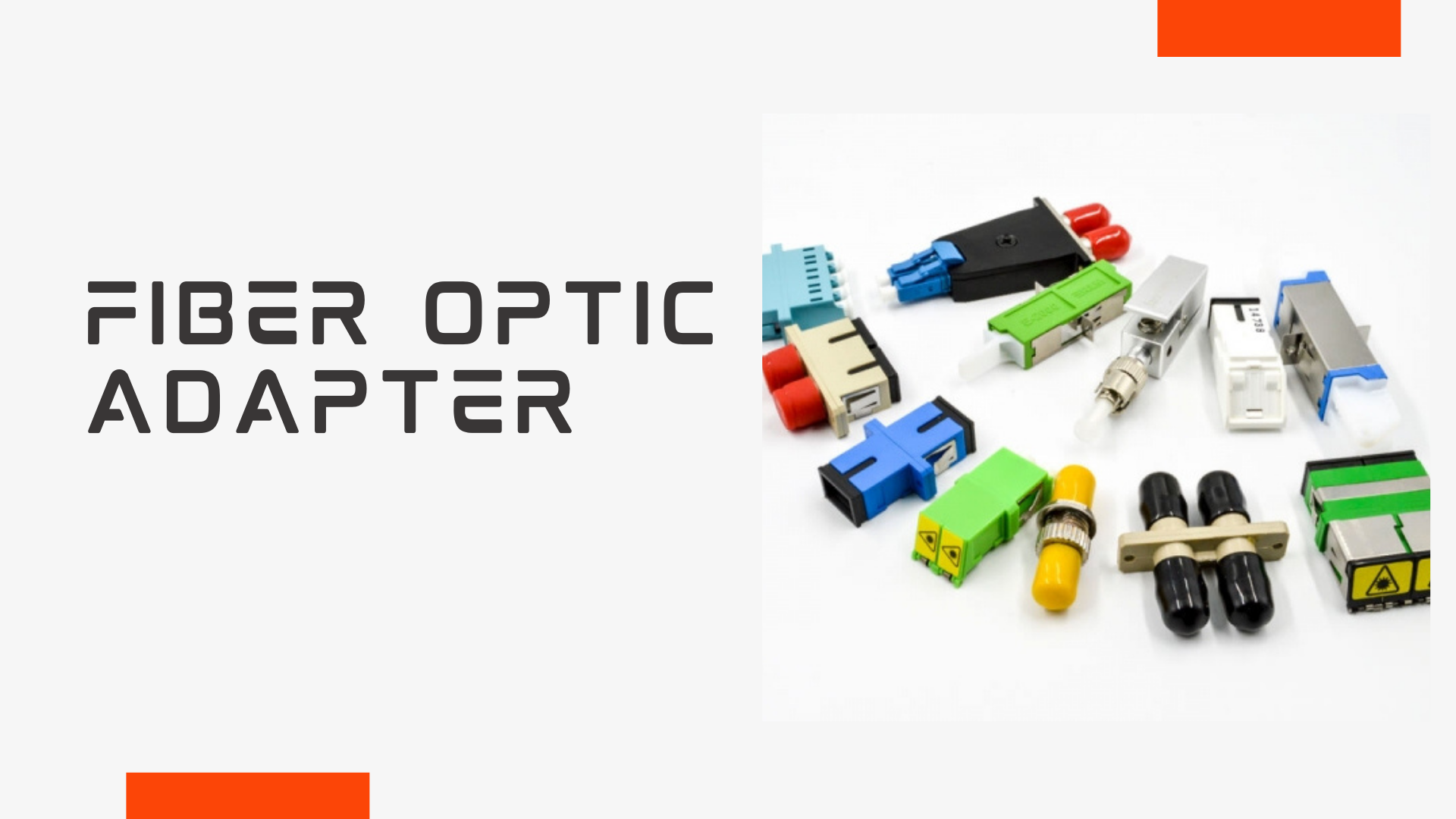
While this adapter itself is small and is part of the small portion of the fiber optic cabling system, it does not diminish its significance in the fiber optical cabling system. As with other fiber optic devices requires cleaning. There are two primary cleaning techniques, which are non-contact and contact cleaning.
- Method for cleaning contact
(1) Paper for wiping dust or a cleaning cloth that is dust-free Make use of dust-free paper dust-free cloths with sewage alcohol to clean the face of fiber optic adaptors.
(2) Cassette type optical fiber cleaning box, a specific purpose for wiping tape is placed inside the casing that rolls, and the concept is to utilize the adhesive strength of the wiping tape to adhere the dirt to the outer side that is the end of the fiber connector.
(3) Pen for cleaning fibers. The fiber-optic cleaning pen is specifically designed to cleanse both the interior and exterior of the adapter as well as the ferrule’s end face. It is a simple process. The refill’s end is placed into the ceramic sleeve on the adapter. It is cleaned in a single press. The end face. - Cleaning methods that do not involve contact
(1) (1) Ultrasonic cleansing method Currently the ultrasonic cleaning equipment available uses this method of cleaning, and the cleaning liquid is transformed to the ultrasonic “liquid column” to be pumped out toward the final face of the connector fiber.
(2) (2) High-pressure blowing technique; the cleaning liquid is displayed on the face that ends the fiber connector and the high-pressure gas then is used to align the final surface of the connector and cleanse the connector’s end face.
How can I make a Fiber Optic Splitter?
In total there are five steps required to make fiber optic splitters. Each step demands strict control and monitoring of different parameters such as temperature, environment and precise control of manufacturing and the equipment.
Step One: Preparation of Components
Typically, three components are required. Three components are required. PLC circuit is embedded in a glass wafer. Each edge of the glass wafer is polished to provide a highly precise flat surfaces and superior quality. The v-grooves are then pressed onto the glass substrate. One or more ribbon fibers are then glued to the substrate of glass. Then, the assembly is polished.
Step Two The third step is to align
Once the 3 components they are then placed on an alignment stage. The output and input fiber array is placed on a goniometer to match up to each other and the PLC chip. The physical alignment between the fiber arrays as well as the chip is monitored by the continuous output of power levels through the optical array.
3. Cure
The assembly is then put inside an room with a UV (ultraviolet) chamber, where it will fully cure at a temperature that is controlled.
Step Four Step Four: Step Four: Packaging
The splitter’s bare end is put in alignment and then welded into the metal housing, where fiber boots are placed on both sides on the body. A testing of the temperature is necessary to confirm the final is in good working order.
The Fifth Step: Optical Testing
When it comes to testing three crucial parameters such as insertion loss uniformity, and polarization dependent loss (PDL) are tested on the splitter to verify that it is in line with the optical specifications of the splitter as per the GR-1209 CORE specifications.
How can you determine the quality of a Fiber Optic Splitter?
The performance of an optic splitter is measured by five parameters that include optical bandpass, the loss of insertion, return loss uniformity, directivity, and. The next section will explain the steps to test each specification.
1. The optical bandpass may be checked using an analyzer of optical spectrum using an extremely powerful light source with an axial wavelength that is the bandpass required. The attenuation of the bandpass should be in line with the requirements of the splitter.
2. The loss of insertion is measured using the light source and power meter. The power level of the reference source is measured and each input port on the optical splitter’s output is tested.
3. Return loss can be analyzed with the return loss meter. It is connected via the input ports to the return loss gauge. all outlets are linked to an non-reflective index match gel.
4. A splitter’s uniformity could be assessed by looking at the results of the insertion loss test in order to make sure that the gap between the loss with the greatest loss and the least loss remains within an acceptable range of uniformity.
5. It is possible to measure the directivity in a way similar to the test for insertion loss. The sources of light and the meter are connected to one port for input as well as two ports for output.
Conclusion
Fiber optic splitters allow the optical signal fiber to be spread across several fibers. Because splitters do not contain electronic components and do not require power they’re an essential component that is widely used in all fiber optical networks. Therefore, selecting fiber optic splitters that help improve the efficiency for optical technology is crucial in creating a network structure that can be used for a long time in the future. sprunki horror Endless Fun Awaits!


